Read-Noise-limited and Photon-Shot-Noise limited regimes

Having examined various imaging conditions in the previous sections, we can see that Dark Shot Noise can be considered negligible – either because we are imaging under bright light conditions, or by TE-cooling the imager if we are imaging under very low-light conditions. This leaves us with two major sources of noise: Photon Shot Noise and Read Noise. The former is a fact of Physics that we can’t do very much about. By choosing a camera that is intended for scientific imaging, we can reduce the latter. The lowest Read Noise cameras that are commercially available are emCCD and sCMOS cameras. These typically cost more than general purpose cameras with higher Read Noise that are suitable for non-quantitative purposes such as taking photographs under relatively bright conditions. Some cost-effective CMOS cameras also have low read noise, and are quite usable in moderately low-light applications.
If the application requires fast imaging under low light conditions, it is definitely worth the price of a low Read Noise sCMOS camera. But this decision should be made with the full knowledge of whether an application can benefit from such a selection.
It is helpful to classify imaging applications in terms of which of the two noise sources is likely to be dominant for a particular situation. This is where the terms Read Noise limited and Photon Shot Noise limited come in.
Recalling Equation #2 from the article titled Signal to Noise Ratio, we had:
Total Noise = Sqrt(Photon_shot_noise2 + Read_noise2 + Dark_shot_noise2)
Total Noise = Sqrt(P*QE*t + Nr2 + Id*t) ——————— [Equation #2]
If Dark Shot Noise is negligible (for reasons provided above), then Equation #2 is simplified to:
Total Noise = Sqrt(P*QE*t + Nr2)
This gives rise to two conditions, depending on which one of these noise sources is dominant.
Read Noise limited: If Nr2 >> P*QE*t, the Read Noise dominates the Photon Shot Noise. For cameras that are not intended for lower light scientific imaging applications, the Read Noise can be quite high. Therefore Nr2 >> P*QE*t is the default case – except when imaging very bright scenes for which the Photon Flux “P” is high enough to overcome the Read Noise. Cameras intended for scientific imaging typically have low Read Noise, therefore Nr2 >> P*QE*t for short exposures and/or very low Photon Flux levels. SNR, for this case can be simplified to:
SNR = Signal/Noise = P*QE*t/Nr
Photon Shot Noise limited (sometimes referred to simply as “Shot Noise limited”): If P*QE*t >> Nr2, it is the Photon Shot Noise that dominates. This is a desirable condition, since this means that it is the incident light and not the camera that is the dominant noise source. This occurs when imaging very bright scenes for which the Photon Flux “P” is high. It is much more of a challenge to reach this condition when imaging under low light conditions: only cameras with very low Read Noise will be Photon Shot Noise limited under low light conditions. In cameras with very low Read Noise this condition will be achieved at relatively short exposures. In cameras with higher read noise, users would have to increase the exposure in order to reach this condition. Being Photon Shot Noise limited is clearly a desirable condition, indeed it is the case of an Ideal Imager (for which Read Noise = 0e–) for any level of Photon Flux. SNR, in the Photon Shot Noise limited regime can be simplified to:
SNR = Signal/Noise = P*QE*t/Sqrt(P*QE*t) = Sqrt(P*QE*t)
The system can be said to transition from being Read Noise limited in its performance to Photon Shot Noise limited in its performance when the two terms are equal, i.e. P*QE*t = Nr2
From the above equation, we can estimate that this “crossover” would occur at an exposure of:
t = Nr2/(P*QE)
For the imager used in our example, QE = 80% and Nr = 2e–, we can compute the following:
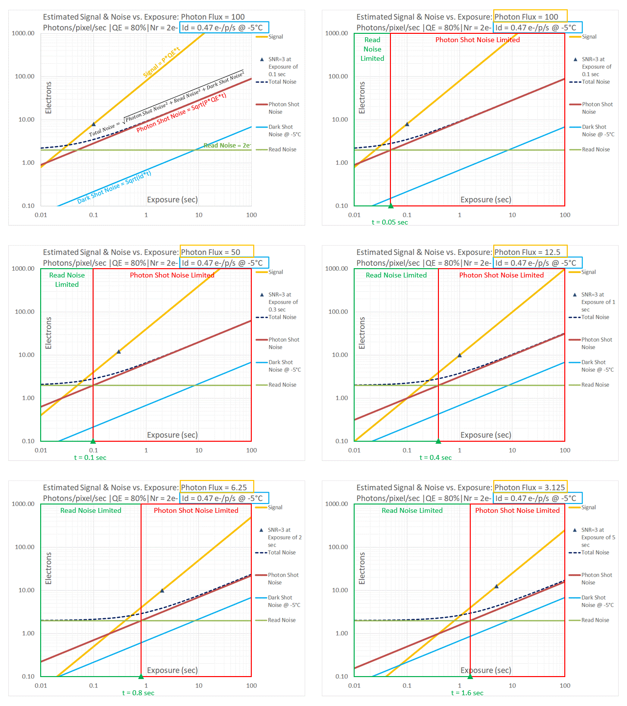
| Photon Flux (photons/pixel/sec) | Nr2/(P*QE) |
| 100 | 0.05 sec. |
| 50 | 0.1 sec. |
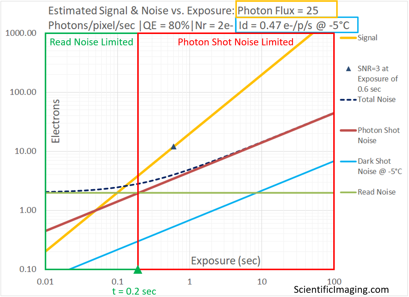
| 25 | 0.2 sec. |
| 12.5 | 0.4 sec. |
| 6.25 | 0.8 sec. |
| 3.125 | 1.6 sec. |
On the now-familiar graph of Signal and Noise vs. Exposure, the crossover from Read Noise limited to Photon Shot Noise limited occurs at the exposure value for which Read Noise = Photon Shot Noise. This is the point where the red line representing Photon Shot Noise and the green line representing Read Noise intersect, as shown below.

We observe that the point of intersection of the lines representing Photon Shot Noise and Read Noise represents the dividing line between two imaging regimes: one in which the performance of the imaging system is Read Noise limited and another in which the performance of the imaging system is Photon Shot Noise limited. Although it is shown as a sharp dividing line between the two regimes, one can see from the curve representing Total Noise (dashed black, on these plots) that the transition is a gradual one. This concept will be useful in the process of selecting a camera that matches the requirements of a scientific imaging application.
In the next article, we will use the information presented and converge on a method that can be used to model the performance of a camera over a wide range of imaging conditions.

