In the previous topic, we developed key figures-of-merit in the form of coefficients that allow us to make efficient comparisons between different imaging technologies under a range of conditions, from very low light to bright light.
Please contact us for assistance in the process of matching the right imager with the requirements of your application. As detailed in the list of prioritized criteria for Scientific Camera selection, it is important to prioritize photonics performance as the first step in the camera selection process.
Coefficients for various cameras
The following coefficients are calculated based on peak QE values for several cameras. The coefficient Ce/P gives us an estimate for the exposure (in sec) at which the corresponding camera will transition from being Read Noise limited to Photon Shot Noise limited for a particular level of Photon Flux Density. For this table, a Photon Flux Density of 1.0 photons/sq-μm/sec is assumed, therefore Ce/P is the same as Ce. The cameras included on this list use sCMOS and CMOS imagers with a fairly wide range of specifications. A similar table can be easily created for any specific wavelength of interest.
Case Study #1: NIR imaging, low light
Here are the salient requirements of an imaging system:
- Wavelength (λ) = 750nm
- Photon Flux Density = 0.5 photons/sq-μm/sec.
- Preference: achieve SNR > 3 images at exposure duration ≈ 1sec.
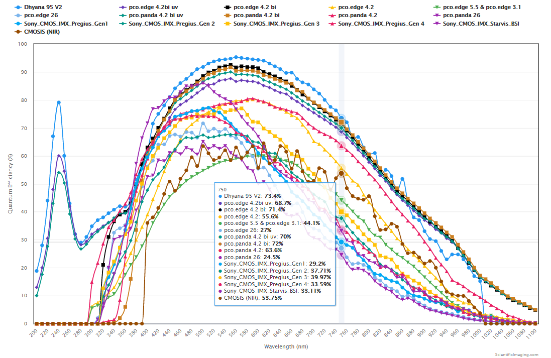
Step #1: From the article titled “QE Curves for sCMOS and CMOS Imagers“, we note the QE values for a wide range of cameras at λ = 750nm. These values are entered into a spreadsheet from which we get the coefficients.
The table below shows the coefficient values based on the QE values at λ = 750nm (highlighted in yellow). To facilitate comparisons at a Photon Flux Density of 0.5 photons/sq-μm/sec, we have shown values for Ce/P instead of Ce. The coefficient Ce/P gives us an estimate for the exposure (in sec) at which the corresponding camera will transition from being Read Noise limited to Photon Shot Noise limited for this level of Photon Flux Density.
Step 2: Since we don’t want our imaging system to be Dark Shot Noise limited, we select only cameras for which the Photon Flux Density is sufficiently >> Ct. A 3x margin is sufficient, therefore we select only those cameras for which Ct < 0.5/3 = 0.17 Photons/sq-μm/sec. Given the low Photon Flux Density in this Case Study, it is not surprising that only TE-cooled cameras are selected on the basis of their low Ct values, highlighted in green in the above table.
Step 3: From the table, we identify the Cr and Cp parameters, knowing that these will determine the estimated SNR for the selected cameras. The graph below gives us an indication as to which cameras will provide the best SNR, all else being equal. At this stage, we may also decide to eliminate the two cameras with the lowest Cr and Cp values – recognizing also that their Ce/P values (see above table) are quite large. This means that it will require exposures of several seconds long to achieve Photon Shot Noise limited imaging.
Finally, since there is no particular benefit in using a UV camera at λ = 750nm, we also eliminate the “pco.edge 4.2 bi UV” camera, keeping its VIS equivalent (the pco.edge 4.2bi) in the mix.
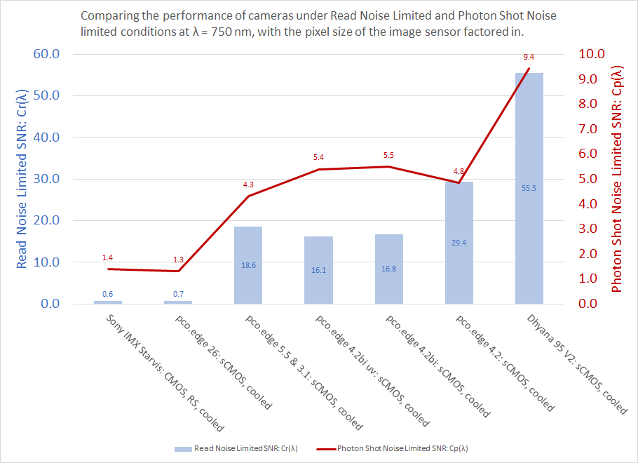
The above graph shows that four cameras meet the “photonics” requirements of the application. These cameras are shown in the table below. Their “photonics” parameters under P=0.5 photons/sq-μm/sec and λ = 750nm are highlighted.
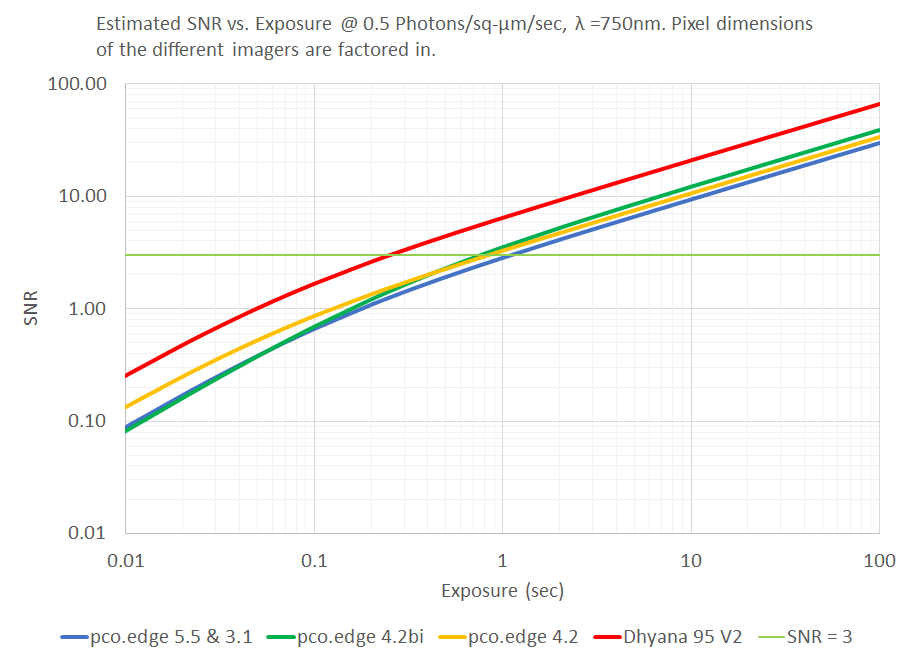
The photonics coefficients can now be used to quantify and compare the estimated performance of the cameras, as shown in the graph below. This allows us to properly evaluate the tradeoffs, for example, we might be in a position to make statements such as: “all else being equal, we can switch from camera A to camera B at a cost of $X, for a 15% improvement in SNR at exposures > 1sec.” Or, “all else being equal, we can improve the SNR of our system by almost 2x by using a camera with 70% larger pixels, being mindful of an accompanying tradeoff in the optical resolution of the system.”
Note that one of the four cameras has been omitted from the graph for the sake of clarity.
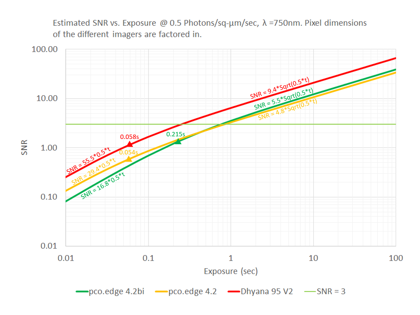
Now that we have used the “photonics” parameters to narrow down the selections to four cameras, we may now use other features related to optics, frame rates, and the price of the cameras to make our final decision.
Case Study #2: Finding a replacement for a Sony ICX285AL application
Scenario: a system designer is seeking to replace a now-obsolete TE-cooled CCD camera which used a Sony ICX285AL imager. Here are the salient requirements of an imaging system:
- Replacement of an obsolete Sony ICX285AL imager
- Wavelength of interest (λ) = 550nm, at which the obsolete camera had a QE of 59% in its “enhanced NIR” or “boost” mode
- Photon Flux Density is not exactly known because there are a wide range of samples and experimental settings.
- samples that emit low light: producing images that are just discernable at exposures of ~10sec with the obsolete camera
- samples that are brighter: producing images that are discernable at exposures of ~200ms with the obsolete camera
- Performance goal: achieve SNR as good or better than that of a Sony ICX285AL at similar exposures, with similar samples
- Additional constraints may exist, for example the size of the imager may be such that it has to be reasonably close to the 2/3″ optical format of the obsolete CCD imager.
- There may also be budgetary constraints, in which case slightly lower performing cameras may be worth considering.
Step 1: Compute the coefficients for the obsolete Sony imager: in the table below the values that are highlighted yellow are from the camera datasheet, while those that are highlighted in light blue are calculated using the formulae for our coefficients.
ICX285AL at 550nm
| Camera | Sony ICX285AL cooled (at λ = 550nm) |
|---|---|
| Cf(λ) = FWC/(a*QE) | 815 |
| Read Noise Limited SNR: Cr(λ) = a*QE/Nr | 4.1 |
| Ce(λ) = Nr²/(a*QE) | 1.47 |
| Photon Shot Noise Limited SNR: Cp(λ) = Sqrt(a*QE) | 5.0 |
| Photon Flux Density must exceed: Ct(λ) = Id/(a*QE) | 0.04 |
| Co = Nr²/Id | 36.0 |
| Dark Shot Noise Limited SNR: Cd(λ) = a*QE/Sqrt(Id) | 24.5 |
| Pix_size (μm) | 6.45 |
| Pix_Area (sq-μm) | 41.60 |
| Peak QE (%) | 59 |
| Nr (e-) | 6 |
| FWC (e-) | 20000 |
| Id (e-/p/s) | 1 |
| At temp (°C) | 0 |
Step 2: Using the above values in the SNR vs. Exposure model, we can estimate the values of Photon Flux Density for both the “low” and the “high” case with the older camera. The model informs us that this camera can achieve an SNR=3 at exposures of 200ms @ 4 Photons/sq-μm/sec and ~10sec @ 0.1 Photons/sq-μm/sec.
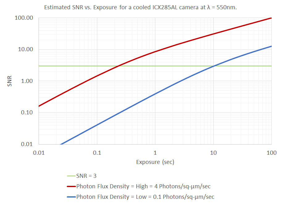
Step 4: Since the “low” Photon Flux Density condition presents the more difficult challenge, we use the Photon Flux Density = 0.1 Photons/sq-μm/sec case to determine which cameras are worth considering.
Step 5: From the table, we identify the Cr and Cp parameters, knowing that these will determine the estimated SNR for the selected cameras. The graph below gives us an indication as to which cameras will provide the best SNR, all else being equal. In this case, we keep the two cameras with the lowest Cr and Cp values even though their Ce/P values (see above table) are quite large. While these cameras may require longer exposures to achieve Photon Shot Noise limited imaging, they may align with our budgetary constraints.
Since there is no particular benefit in using a UV camera at λ = 750nm, we also eliminate the “pco.edge 4.2 bi UV” camera, keeping its VIS equivalent (the pco.edge 4.2bi) in the mix. The Dhyana 95 V2 leads the pack in terms of performance, but the large (31.9mm, diagonal) size of its imager would not typically be ideal for a drop-in replacement for an ICX285AL with a 2/3″ optical format (11mm diagonal).
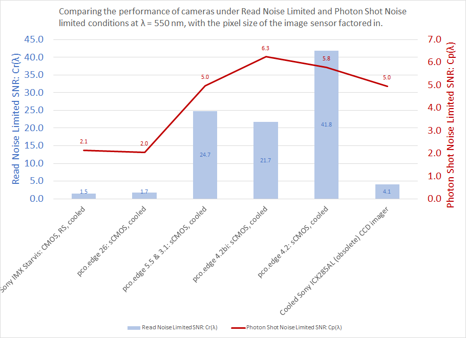
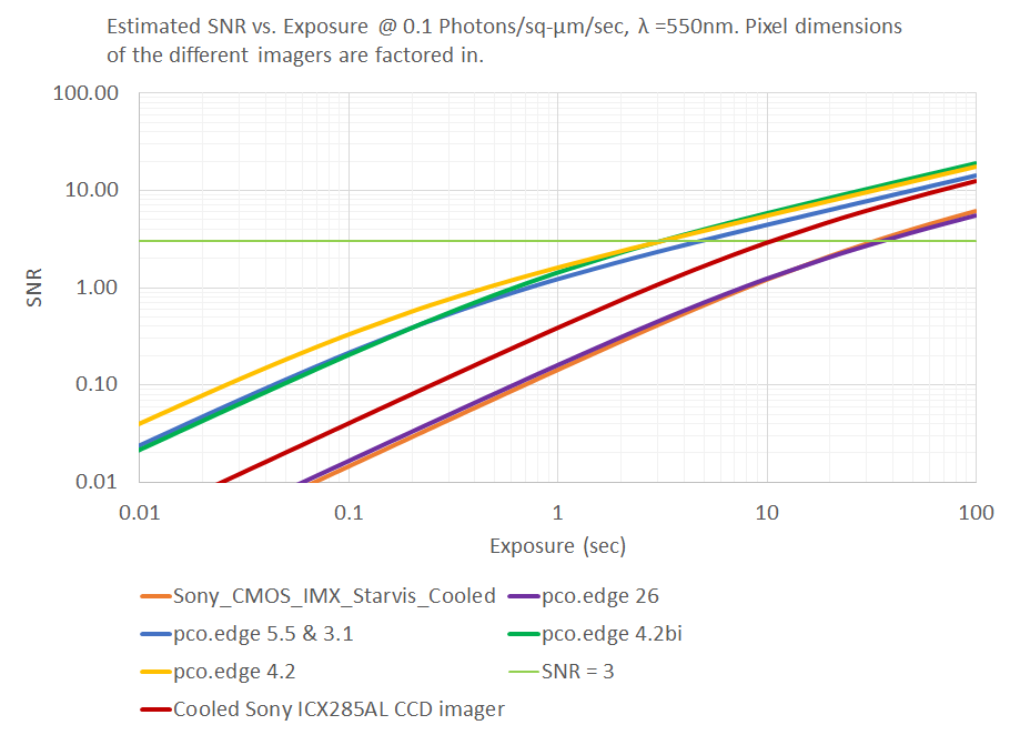
The information that is shown in the SNR graph above is re-cast in the rSNR (Relative SNR) graph below, to make the performance differences easier to see. Note that the y-axis of the rSNR graph is linear, not logarithmic. It is clear that there are four cameras (pco.edge 4.2, pco.edge 4.2bi and pco.edge 5.5 and pco.edge 3.1) that can be used to improve the imaging performance under the low-light conditions of this application. A cooled Sony CMOS IMX Starvis camera may be considered if longer exposures than those of the ICX285AL are worth the cost tradeoff.
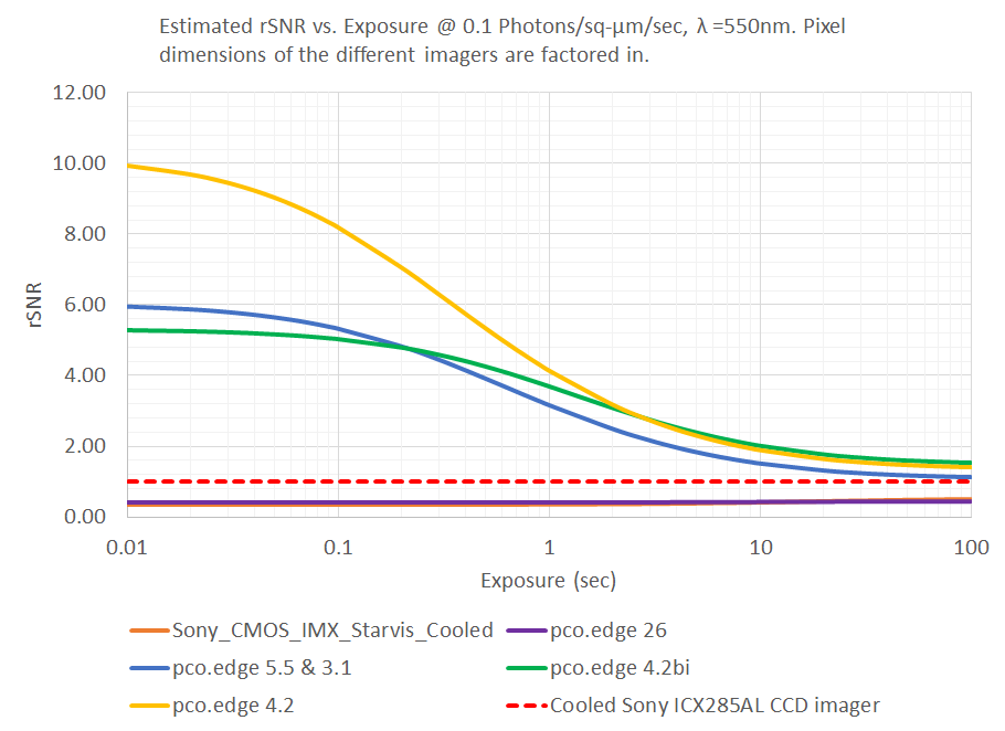
The cameras that were found to be good replacements in the low Photon Flux Density case of this application will also work well in the higher Photon Flux Density case.
In the next section, we consider the brighter light [Photon Flux Density = 4 Photons/sq-μm/sec] case as a separate problem to solve. Since bright-light applications do not typically require cooled cameras, we change the example to that of replacement of a non-cooled ICX285AL CCD.
Case Study #3: Replacement of a non-cooled ICX285AL CCD camera
Scenario: a system designer is seeking to replace a now-obsolete non-cooled CCD camera which used a Sony ICX285AL imager. Here are the salient requirements of an imaging system:
- Replacement of an obsolete Sony ICX285AL imager
- Wavelength of interest (λ) = 550nm, at which the obsolete camera had a QE of 59% in its “enhanced NIR” or “boost” mode
- Photon Flux Density =4 Photons/sq-μm/sec
- Performance goal: achieve SNR as good or better than that of a Sony ICX285AL at similar exposures, with similar samples
- Additional constraints may exist, for example the size of the imager may be such that it has to be reasonably close to the 2/3″ optical format of the obsolete CCD imager.
- There may also be budgetary constraints, in which case slightly lower performing cameras may be worth considering.
Step 1: Compute the coefficients for the obsolete Sony imager: in the table below the values that are highlighted yellow are from the camera datasheet, while those that are highlighted in light blue are calculated using the formulae for our coefficients. The difference between a cooled version that we considered in the previous example and a non-cooled version is the dark current Id. This impacts only the Ct & Cd coefficients of the imager which have a dependence on Id. The dark current Id is estimated to be 15e–/p/s for a non-cooled version of this CCD.
| Camera | Sony ICX285AL non-cooled (at λ = 550nm) |
|---|---|
| Cf(λ) = FWC/(a*QE) | 815 |
| Read Noise Limited SNR: Cr(λ) = a*QE/Nr | 4.1 |
| Ce(λ) = Nr²/(a*QE) | 1.47 |
| Photon Shot Noise Limited SNR: Cp(λ) = Sqrt(a*QE) | 5.0 |
| Photon Flux Density must exceed: Ct(λ) = Id/(a*QE) | 0.61 |
| Co = Nr²/Id | 2.4 |
| Dark Shot Noise Limited SNR: Cd(λ) = a*QE/Sqrt(Id) | 6.3 |
| Pix_size (μm) | 6.45 |
| Pix_Area (sq-μm) | 41.60 |
| Peak QE (%) | 59 |
| Nr (e-) | 6 |
| FWC (e-) | 20000 |
| Id (e-/p/s) | 15 |
| At temp (°C) | 25 |
Step 2: Omitting cooled cameras from consideration, we find that for a Photon Flux Density of 4 Photons/sq-μm/sec, there are many choices. We can consult the table shown in Step 4 (in Case Study #2) and examine the following cameras as potential candidates.
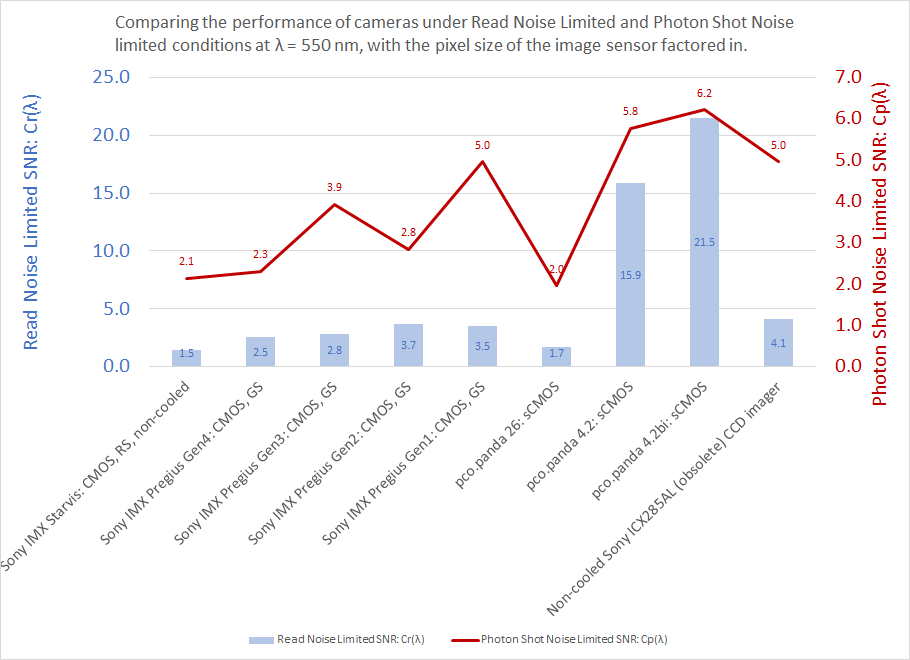
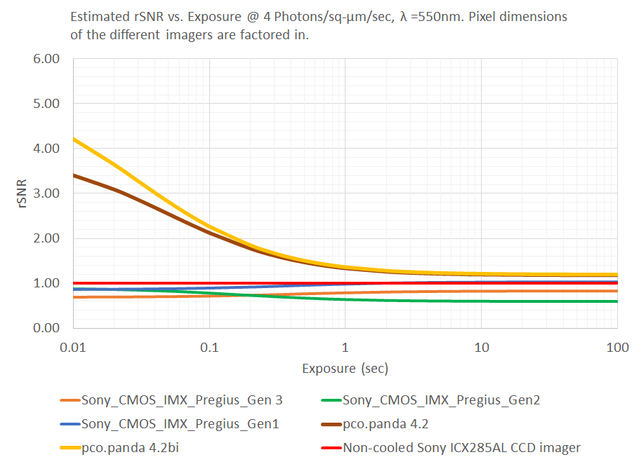
In the Relative SNR graph below, we observe that non-cooled sCMOS cameras (pco.panda 4.2bi and pco.panda 4.2) significantly outperform the non-cooled ICX285AL – as also indicated in the graph of coefficients shown above. These cameras would be a good choice if the goal is to improve performance of the imaging system.
Cost effective non-cooled CMOS cameras based on Sony Pregius Gen 1, Gen 2 and Gen3 CMOS imagers are also worth considering if the goal is to achieve close to parity in performance at a significantly lower price point. These CMOS imagers have smaller pixel sizes, which is why they achieve lower SNR than imagers with larger pixels (all else being equal). However, one may achieve higher SNR with these cameras by using Binning (e.g. 2×2 or 3×3) to cover the same field-of-view with effectively larger pixels. There are many choices in terms of #MPix and imager sizes available within the Gen 2 and Gen 3 families of Sony CMOS imagers.
Please contact us for assistance in the process of matching the right imager with the requirements of your application. As detailed in the list of prioritized criteria for Scientific Camera selection, it is important to prioritize photonics performance as the first step in the camera selection process.

