In this article, we take a deeper dive into two qualitative Phase-Based imaging techniques that were introduced in the previous article “M11) Label-Free Imaging Techniques in Life Science Microscopy“.
- Phase Contrast (Zernike) – simple, robust contrast in live cells
- Differential Interference Contrast (DIC) – edge-enhanced detail, good for thicker samples
The next article will delve into two quantitative Phase-Based imaging techniques:
- SLIM (Spatial Light Interference Microscopy): well suited for optically thin samples
- GLIM (Gradient Light Interference Microscopy): optimized for thick, 3D specimens
Theory
For a biological specimen, the thickness and refractive index inhomogeneity determine how much light scattering it produces. It is scattering rather than absorption that determines the ultimate contrast of the image, as in the visible spectrum most cells and tissues do not absorb significantly.
The scattered light generated in single cells and thin tissue slices is orders of magnitude weaker than the incident light. This class of specimens is referred to as ‘phase objects’, as they significantly impact only the phase of the incident field and not the amplitude. Conventional staining and the use of fluorescent tags converts them into ‘amplitude objects’ and while these stains and tags offer high-contrast imaging with molecular specificity, they are often qualitative and sample-preparation dependent, while photobleaching and phototoxicity limit fluorescent imaging of live cells.
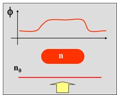
Phase Imaging microscopy techniques take advantage of the fact that changes in the refractive index and thickness of “phase objects” (live, transparent cells and tissues) results in a slight delay in the phase of light passing through them. Such objects don’t significantly change the amplitude or intensity of the light, but they do cause a phase shift Φ, or an optical pathlength (OPL) change. This change would not be discernible by the human eye, and a viewing such samples on a conventional brightfield microscope would not be very useful.
Phase Contrast Microscopy — Bringing Transparent Cells into View
Phase contrast microscopy, introduced by Frits Zernike (Nobel Prize in Physics, 1953), revolutionized live-cell imaging by enabling visualization of transparent, unstained specimens that otherwise appear invisible under a bright-field microscope.
How It Works
In Phase Contrast Microscopy, the phase shifts are converted into intensity differences, making structures like nuclei, organelles, and cell boundaries visible without staining.
Optical Design Essentials
- Condenser Annulus
A ring-shaped aperture in the condenser shapes the illuminating light into a hollow cone. - Phase Plate
Placed in the objective’s back focal plane, the phase plate imparts an additional ±90° phase shift to light that did not pass through the specimen (i.e., the background light). - Interference & Contrast Enhancement
The phase-shifted background light and the diffracted light (carrying sample detail) interfere constructively—brightening the image of structures. A neutral density ring then reduces the background light by ~70–90%, further enhancing contrast.
Cameras recommended for Phase Contrast Microscopy: CMOS Cameras and sCMOS Cameras
Differential Interference Contrast (DIC) Microscopy — Revealing Optical Path Gradients
Differential Interference Contrast (DIC) microscopy, developed by Georges Nomarski in 1952, enhances contrast in transparent, unstained specimens by converting subtle differences in optical path length—caused by variations in refractive index or thickness—into visible intensity gradients. The resulting image appears with a pseudo-three-dimensional “relief” effect, revealing fine details invisible in bright-field microscopy.
How It Works
DIC transforms minute phase differences between adjacent points in the specimen into amplitude (intensity) differences. These gradients of optical path length are detected as variations in brightness and shadow, emphasizing edges and internal structure.
Optical Design Essentials
- Polarizer
An initial polarizer converts unpolarized illumination into linearly polarized light, providing a controlled starting state for interference. - Nomarski (or Wollaston) Prism – Beam Shear
A birefringent prism splits the polarized beam into two orthogonally polarized rays that are slightly displaced (“sheared”) laterally. Each ray passes through a slightly different region of the specimen, sampling adjacent optical paths. - Specimen Interaction
As the two rays traverse regions of differing refractive index or thickness, each accumulates a distinct optical path length, resulting in a small phase difference. - Second Prism & Analyzer — Recombination
After passing through the specimen and objective, a second prism recombines the beams. An analyzer (a second polarizer, oriented nearly perpendicular to the first) converts their phase difference into intensity variation by interference. - Resulting Contrast
Regions where the optical path length changes sharply appear bright on one side and dark on the other, producing the characteristic shadow-cast, relief-like image. The intensity variation corresponds to the gradient of optical path length rather than its absolute value, emphasizing edges and fine detail in transparent samples.
Comparing DIC and Phase Contrast — Two Routes to Phase Visualization
While both Phase Contrast and Differential Interference Contrast reveal transparent specimens without staining, they visualize different aspects of phase information and create distinct visual impressions.
Mechanism of Contrast
- Phase Contrast converts absolute phase shifts in transmitted light into brightness differences. It employs a condenser annulus and a phase plate in the objective’s back focal plane to produce constructive or destructive interference between diffracted and background light.
- DIC, by contrast, detects the gradient of optical path length between adjacent points. It uses birefringent prisms and polarized light to translate these spatial phase differences into intensity variations. The resulting image accentuates edges, slopes, and refractive-index gradients rather than uniform thickness regions.
Visual Appearance
- Phase Contrast produces a soft-edged image with characteristic halos around structures, useful for highlighting whole cells or organelles.
- DIC yields a crisp, shadow-cast “relief” appearance—bright on one side, dark on the other—mimicking topographic shading. The direction of this pseudo-relief is determined by the prism’s shear orientation.
Practical Considerations
- DIC requires precision alignment of polarizers, prisms, and the analyzer; phase contrast is easier to implement but more prone to halo artefacts.
- Because DIC relies on polarization optics, it may interact with birefringent specimens or reflective surfaces; however, it offers higher apparent resolution and contrast for fine structures.
- In label-free imaging workflows, phase contrast is ideal for general live-cell observation, while DIC excels when visualizing subtle internal gradients, membrane contours, or surface features.
Cameras recommended for DIC Microscopy: CMOS Cameras and sCMOS Cameras
