Noise sources that are unrelated to photons
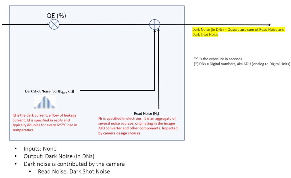
The previous article dealt with Photon Shot Noise, the noise that exists in an imaging system due to the nature of light. In this article, we delve into two major sources of noise that are contributed by the camera, independent of the incident photons: Dark Shot Noise and Read Noise. These are temporal phenomena that one observes in all image sensors, and since they are not dependent on the photons, they can be categorized as Dark Noise. The terms Dark Shot Noise and Read Noise were defined qualitatively in a previous Knowledge Base article. After describing them briefly, we will proceed with a quantitative modeling of both terms. Then, in the next article, we will bring all the signal and noise terms together with the intent of integrating this information into a broader, usable methodology.
Read noise is a term used to describe the temporal variation caused by non-idealities in the measurement process. Although it is typically specified as a number of electrons (for example, read noise = 2e–), it is an aggregate of several different non-idealities. It includes the temporal variations introduced in the process of transferring charges from each pixel, converting charges to a voltage waveform and then digitizing the waveform. Some of these factors are dependent upon the imager, but it is also a function of the design, partitioning and layout of the camera electronics. For this reason, different cameras that use the same imager may have different values for their read noise. The temporal variation represented by “read noise” is a function of the imager used, the clock rate and the level of care taken by the camera designer to protect the signal from interference.
Read noise can depend on the choice of the imaging technology, for example cameras with sCMOS image sensors typically have a lower read noise as compared with most CCD or CMOS cameras. Read Noise also depends very significantly on the camera design techniques. In cameras that are designed for use in low-light scientific imaging applications, everything, from size/enclosure design to circuit board layout is done with the goal of minimizing noise, with read noise being a primary concern. In cameras that are designed for use in less stringent bright-light applications, a camera designer may focus, for example, on reducing the size/cost of the camera while permitting some tradeoffs in read noise.
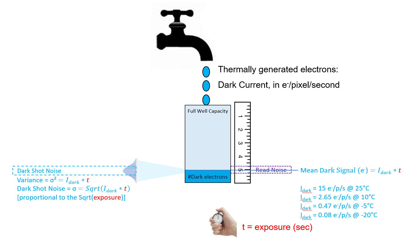
Dark shot noise results from the fact that even if there is no light at all falling on a pixel, the photodiode “faucet” still has a small flow of “leakage” electrons that are generated thermally. In the article titled The Photoelectric Effect in Image sensors, the energy from a photon was shown to create an mobile photoelectron. Thermal energy can also cause mobile electrons to be generated. Thermally generated electrons are not photoelectrons, but they too collect in the depletion region “bucket”. The flow of thermally generated electrons is called dark current because such electrons flow even when there is no light.
Dark current is specified in terms of electrons-per-second (e–/p/s) for each pixel. When the charge accumulated in a pixel is read out there is no way to tell thermally generated “leakage electrons” apart from photoelectrons. Therefore, this dark current adds uncertainty in the total number of electrons that are measured. At longer exposures, dark current can fill up more of the full-well-capacity of the “bucket” thereby reducing the available space for photoelectrons. In addition to using up some of the capacity for photoelectrons, there is a temporal variation in the number of dark electrons collected from one exposure to the next. This temporal variation is referred to as dark-shot-noise. Since it can be modeled as a Poisson distribution, the dark-shot-noise is estimated to be the square root of the number of dark signal electrons that are expected to be captured in each exposure. Since Dark Current is a thermal phenomenon, its effect (Dark Shot Noise) can be mitigated by cooling the image sensor.

Block Diagram, showing Dark Noise only

Graphical Analysis of Dark Noise
In this section, we construct a graphical model that shows Dark Shot Noise and Read Noise on a graph that is similar to the model that was developed for Photon Shot Noise. We place these terms in our quantitative model by first examining them separate from Photon Shot Noise, conceptually “turning off the light” initially for the sake of convenience. In reality, all these noise sources exist together – in fact, what we observe in a camera is a Signal with temporal uncertainty. It is for the sake of conceptual convenience that we categorize Signal and Noise separately, followed by a sub-categorization of the “components” of Noise, which we sometimes aggregate as “Total Noise”.
For the purposes of this article, Total Noise refers to the aggregate of Read Noise and Dark Shot Noise, which is way to quantify the temporal uncertainty that one would observe in the output of a camera in the absence of light). In the next article, we will conceptually “turn on the light” and use the same term (Total Noise) to aggregate ALL sources of noise, including Dark Shot Noise, Read Noise and Photon Shot Noise.

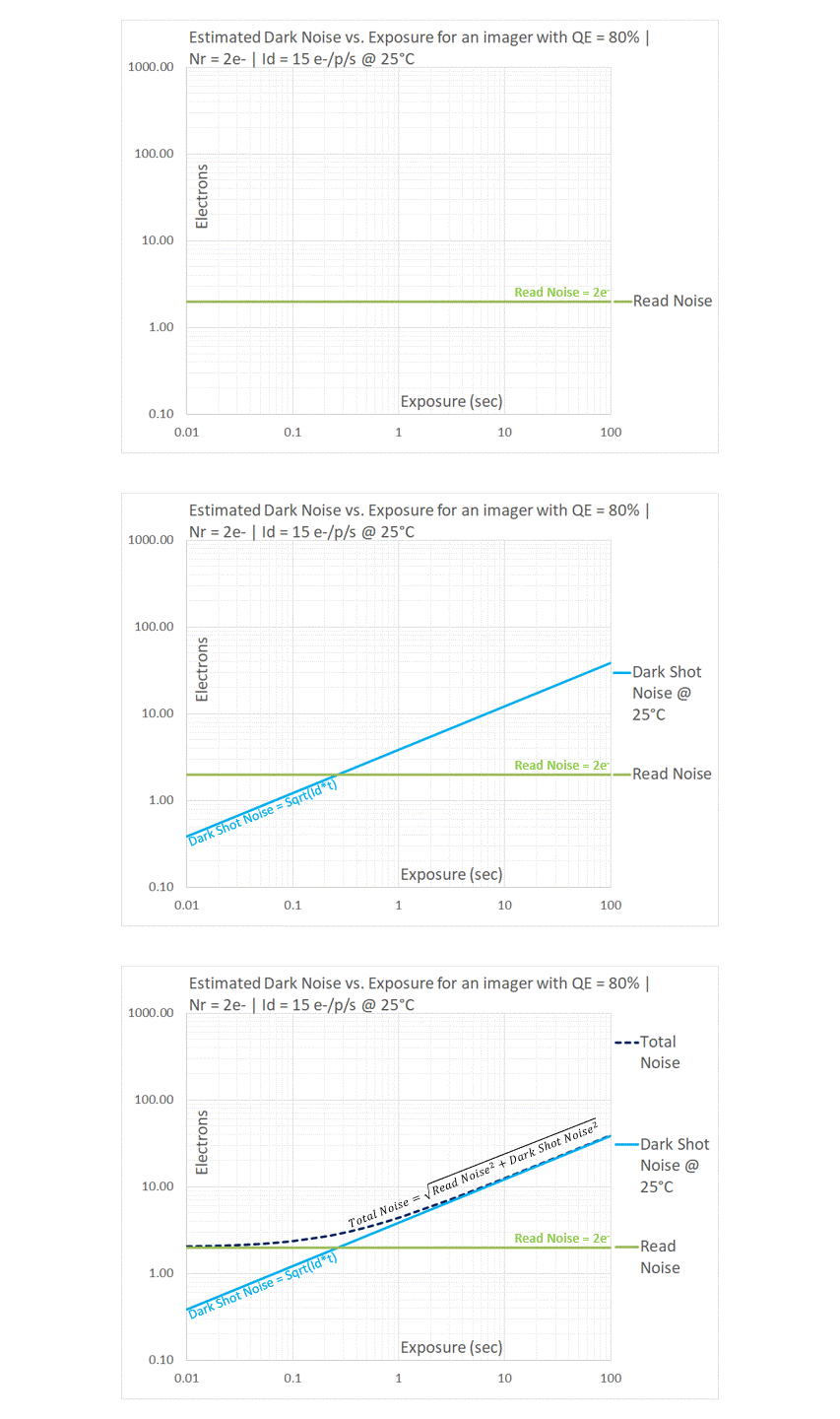
Read Noise is the measurement uncertainty for every pixel of every frame that is readout of an imager, but it does not vary with exposure. Nor does it have a first order dependence on temperature. It is therefore shown as a horizontal line in the above graph. As explained above, Dark Shot Noise is the Sqrt(Dark_Current*Exposure). This is why it is shown on the log-log graph above as a straight line with a slope of 1/2, rising one decade for two decades of exposure. Since Dark Current has a strong dependence on temperature, we use the value of Dark Current for a specified temperature (25°C in the above example). Noise theory tells us that uncorrelated sources of noise must be added in quadrature: for this reason, Total Dark Noise is estimated to be the quadrature sum of the two uncorrelated noise sources. It is obvious from the graph that the Dark Noise follows the higher of the two sources: it is asymptotic to the Read Noise line at shorter exposures, but follows the Dark Shot Noise at longer exposures. This concept is key to understanding the benefits of using cooled image sensors for long exposures, and why there is not much benefit in using cooled image sensors in applications with shorter exposures.

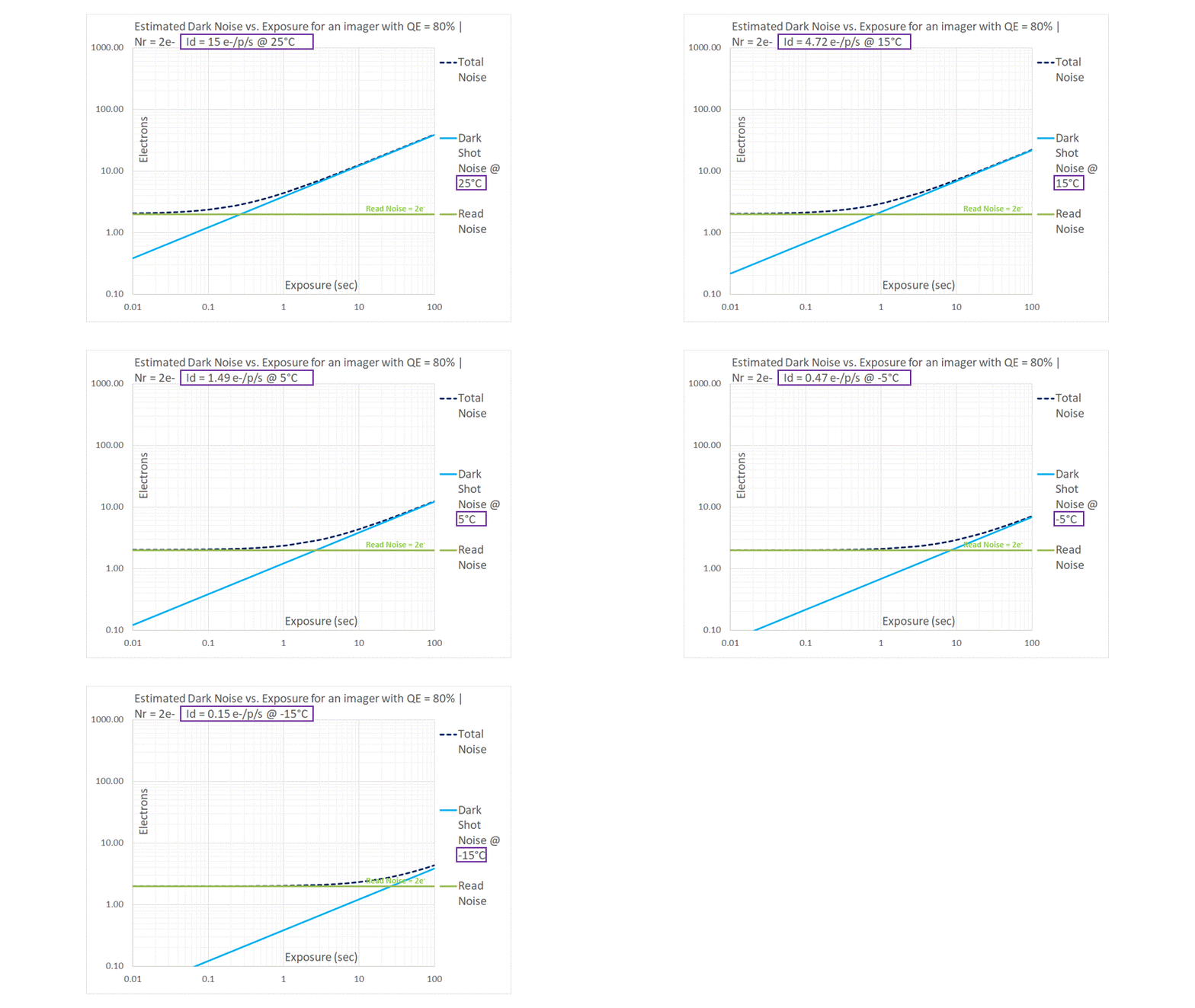
The Dark Current (which is referred to as Id, or Idark in the above figures) for a typical Silicon-based imager doubles for every 6~7°C rise in temperature. In the sequence, we begin at a room temperature of 25°C and then proceed to drop the temperature in 10°C steps. For this analysis, we have assumed that Dark Current drops by a factor of 2 for every 6°C drop in temperature, effectively dropping by a factor of 3.2 for every 10°C drop. The blue line representing Dark Shot Noise moves downwards in a parallel fashion, maintaining its slope of 1/2 on the log-log graph. The main takeaway is that Dark Shot Noise can be pushed down by cooling the image sensor. Without cooling, images taken at longer exposures may be Dark Shot Noise limited. When an imager is cooled, we are able to use it for longer exposures while still being Read Noise limited. This observation gives us a key insight that will be utilized in the next topic, when we use our graphical model to examine some real-world imaging scenarios.
Having grasped key insights by modeling the various components of noise separately, it is now time to put them all together. In the next topic, we bring the Signal and Noise together in order to develop an effective model to compare different types of image sensors under real-world conditions.

