The Real World
In the previous articles we had separated the Signal – a representation of the irradiance in the sample plane that we want to capture – from the various sources of temporal Noise that must be overcome in order to create a useful image. These noise sources include Photon Shot Noise, the uncertainty imposed by light itself, and Dark Noise which is contributed by the camera. We learned that Dark Noise itself comprises of Read Noise and Dark Shot Noise. In this article, we will bring all the signal and noise terms together, as they exist in the real-world. From this exercise, we can conceptualize two distinct imaging regimes, which we describe as being read-noise-limited, or shot-noise-limited. Since this terminology is applicable to all imaging systems, it gives us a useful method by which to characterize an imaging system comprising of real-world components. We can apply this knowledge in selecting the appropriate image sensor technology for a particular application, by understanding which parameters have the most impact on the Signal-to-Noise ratio in each of the two imaging regimes.
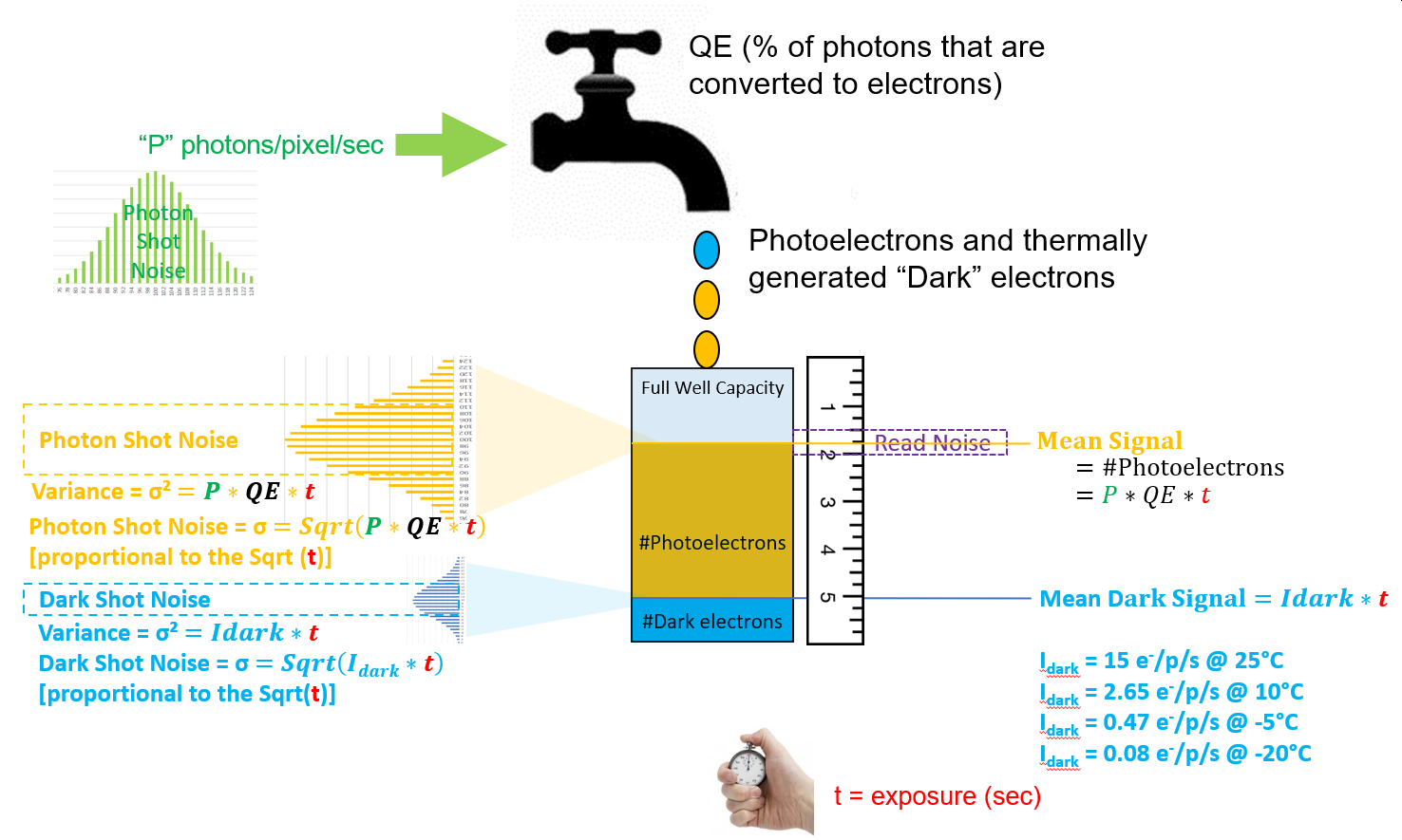
Block Diagram
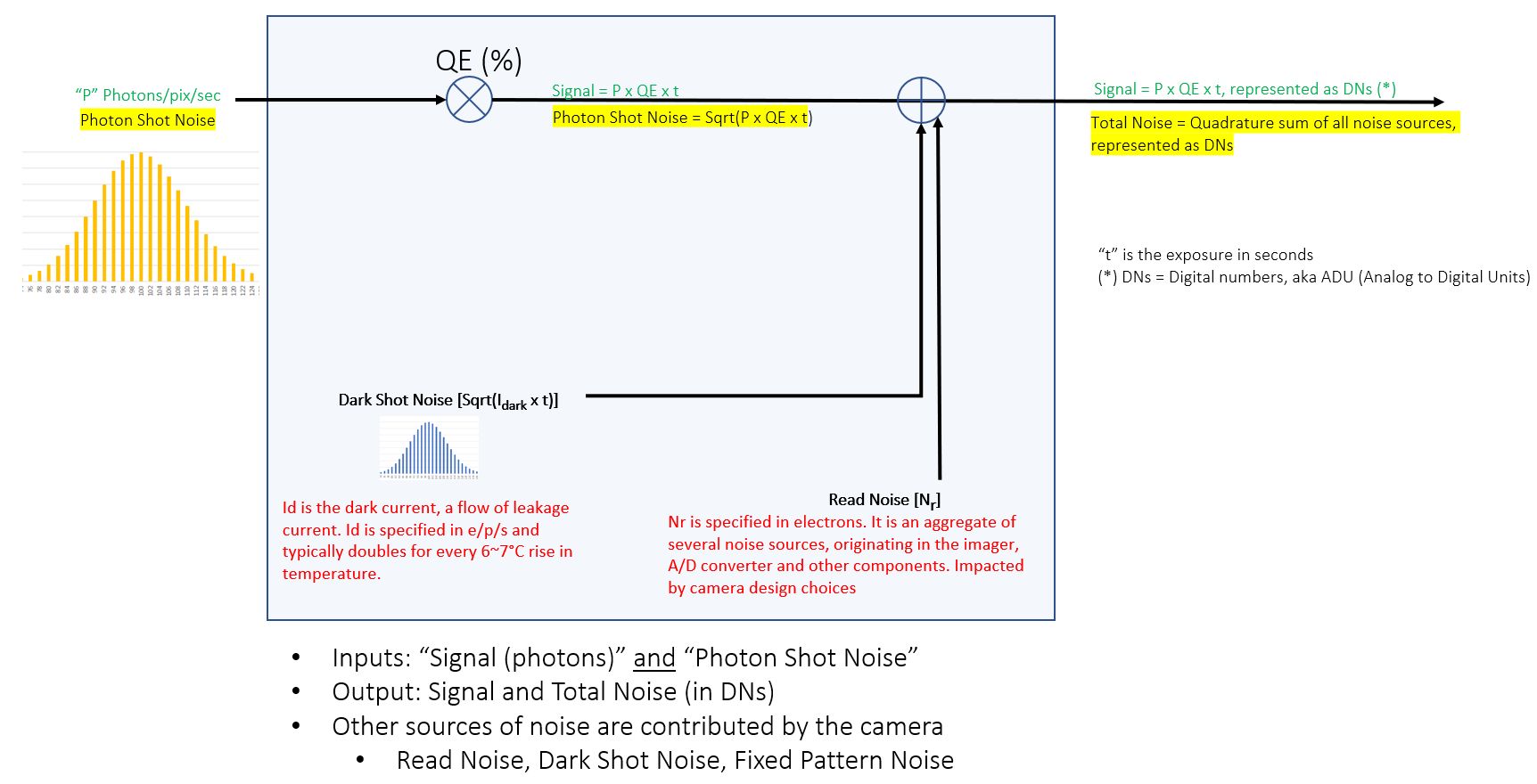
Graphical Analysis
In this section, we construct a graphical model that shows the Signal and the three major sources of temporal noise that must be overcome to produce a useful image.
For the purposes of this article, Total Noise refers to the aggregate of Photon Shot Noise, Read Noise and Dark Shot Noise.
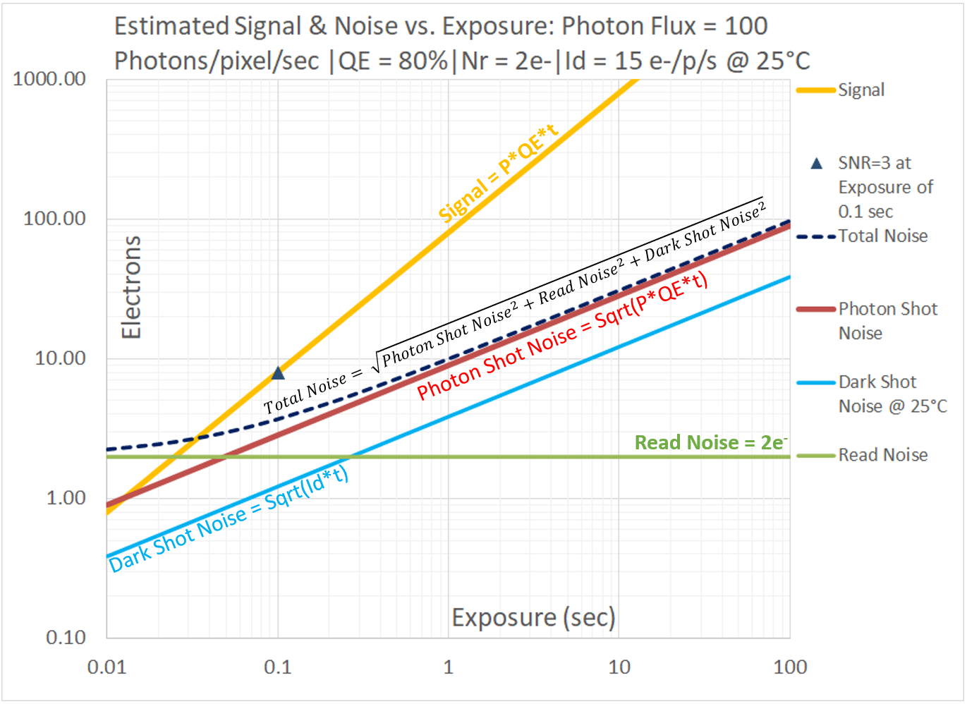
Photon Flux is directly proportional to exposure, hence the golden-yellow line representing Photon Flux has a slope of 1, rising one decade for every decade in exposure. The red and blue lines representing Photon Shot Noise and Dark Shot Noise respectively have a slope of 1/2, due to the square-root relationship: they rise one decade for every two decades in exposure. The green line representing Read Noise is horizontal, since Read Noise does not change with exposure. Total Noise, shown as a dashed black curve, is the quadrature sum of Photon Shot Noise, Dark Shot Noise and Read Noise.
At very short exposures, the dashed black curve that represents Total Noise is asymptotic with the Read Noise line, but as the exposure increases, Photon Shot Noise becomes more dominant and Total Noise begins to track with Photon Shot Noise. Dark Shot Noise is much lower than Photon Shot Noise and therefore its contribution to Total Noise is negligible under this condition. It is worth noting that for under these conditions (Photon Flux of 100photons/pixel/sec), the imaging system is estimated to achieve an SNR=3 at an Exposure of 0.1sec. Also, for exposures exceeding ~0.1sec the dominant source of noise is Photon Shot Noise. One may infer that for exposures longer than ~0.1sec, the imaging system behaves in a Photon-Shot-Noise-dominant manner similar to that of an ideal imager, but with a QE of 80% instead of 100%. This graph is meant to be used as a baseline in the comparisons below, to show how things change with different levels of Photon Flux, and with different camera parameters.
Signal and Noise under low-light conditions
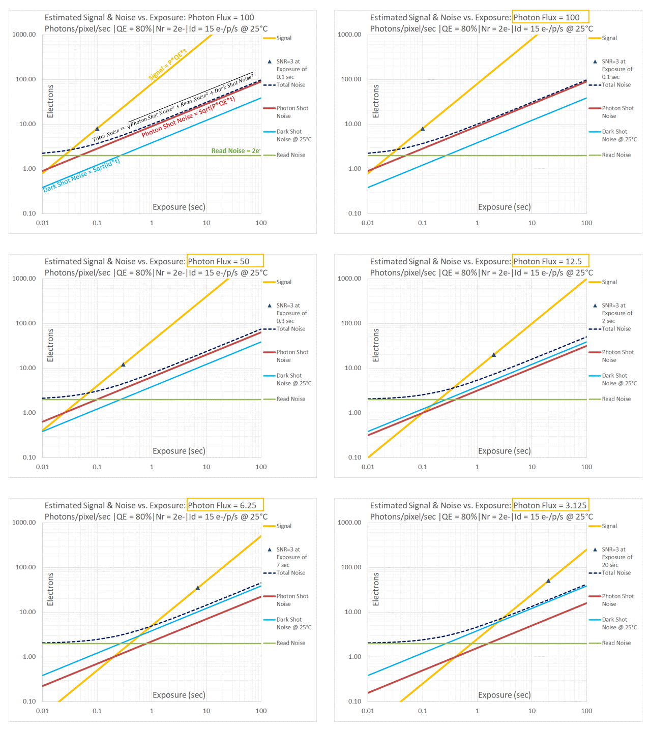
Note that in the above sequence the Read Noise (green line) and Dark Shot Noise (blue line) do not change. This is not a surprise, since Read Noise and Dark Shot Noise are components of “Dark Noise” and are not dependent on the Photon Flux. The golden-yellow line representing the Signal and the red line representing Photon Shot Noise move downwards, while maintaining their respective slopes of 1 and 1/2.
If one keeps an eye of Total Noise (dashed black line), one gets a sense of which noise source is dominant. In all cases, Total Noise tracks with Read Noise at the low exposures for which the Photon Flux does not produce much signal. Consequently there is not much Photon Shot Noise either, and Read Noise dominates. For each level of Photon Flux, there is an exposure above which Total Noise no longer tracks Read Noise: it typically starts to track with EITHER Photon Shot Noise OR Dark Shot Noise, depending upon which one is larger in magnitude.
At higher levels of Photon Flux, the Photon Shot Noise (red line) is much larger than the Dark Shot Noise (blue line). Once a threshold exposure is reached, Total Noise tracks with Photon Shot Noise and our imaging system is Photon Shot Noise limited.
As Photon Flux decreases, the Photon Shot Noise gets closer to the Dark Shot Noise line. Since Total Noise is a quadrature sum of all noise sources, one observes that the dashed black line starts to separate from the red line. This is telling us that the Dark Shot Noise is no longer negligible in comparison to Photon Shot Noise.
Note that between a Photon Flux of 25 Photons/pixel/sec and 12.5Photons/pixel/sec, the relative positions of the red line (representing Photon Shot Noise) and the blue line (representing Dark Shot Noise) get swapped. At these low levels of Photon Flux, the imaging system is Dark Shot Noise limited. Since we know that Dark Shot Noise is the only noise source that has a temperature dependence, this points to a solution that was initially indicated in the previous article titled “Dark Noise”: one may cool the imager and push down the Dark Shot Noise, making the imaging system Photon Shot Noise limited – closer to ideal imager behavior!
To cool … or not to cool?
In this section we begin with the lowest Photon Flux condition from the above sequence. At a Photon Flux of 3.125Photons/pixel/sec, our imaging system was severely Dark Shot Noise limited. It would take an exposure of 20s to achieve an image with SNR=3. Exposures of such duration would be likely to expose another weakness of image sensors, referred to as “hot pixels”. These are pixels in which the dark current is significantly higher than the normal dark current of pixels in a particular imager. Hot pixels are a result of variations in the manufacturing process of imagers. When non-cooled cameras are subjected to long exposures, in addition to the Dark Shot Noise, one may encounter bright points in the image that correspond to pixels with higher dark current.
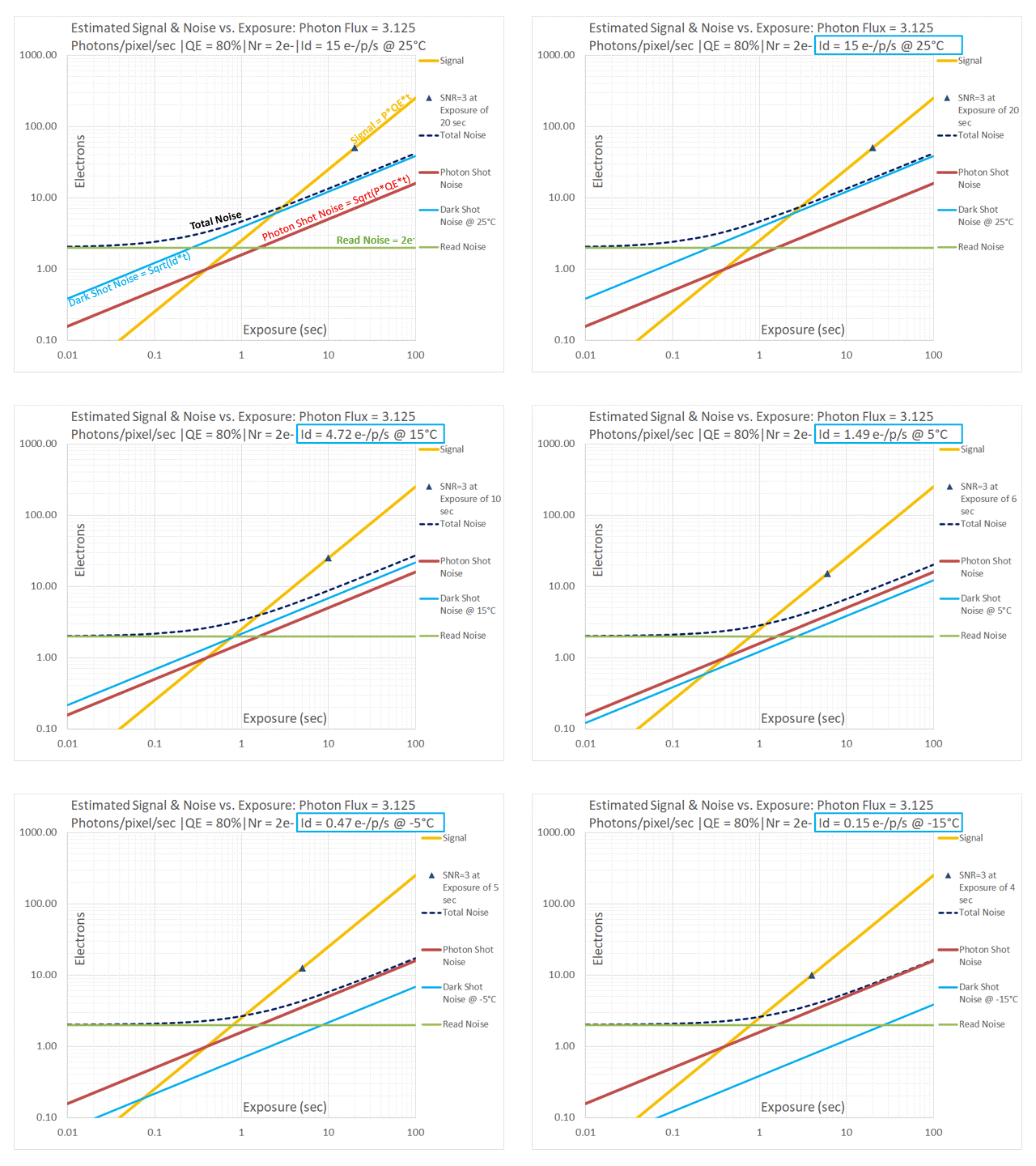
As described in the Knowledge Base article titled “Dark Noise”, the dark current drops by a factor of ~3.2 for every 10°C drop in temperature. Our imaging system that was severely Dark Shot Noise limited at 25°C becomes Photon Shot Noise limited at temperatures below 5°C. This means that our imager, when cooled, starts behaving more like an ideal imager for this type of very low light imaging. We can also see that the exposure at which SNR=3 is achieved changes considerably: from 20s @ 25°C to 5s @ -5°C.
TE-cooling an imager is not without some downside, mostly related to cost, size/weight and – depending upon the camera manufacturer – reliability. Most of the reliability issues arise from the fact that when an imager is cooled to a temperature below the dew point, moisture would condense on it: this degrades image quality. Over time, the exposure to moisture may also damage the imager. For this reason, camera manufacturers enclose the imager and its TE-cooler in a sealed chamber, often backfilled with a dry, inert gas and with an optical window in the front. The design also requires a method of connecting the sensor to downstream electronic components while minimizing the thermal path to the outside of the chamber. Finally, a TE-cooled camera must have a method of dissipating the heat that is drawn away from the sensor.
The following is a link to TE-cooled sCMOS cameras.
The following is a link to TE-cooled CMOS cameras.

